 |
|
7. ADDITIVE DECOMPOSITION
Assume that we are given
a Mealy type automaton ![]() and the partition
and the partition![]() .
To illustrate each step of decomposition with an example, we will use some
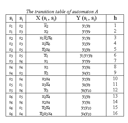
defined automaton A, and partition
.
To illustrate each step of decomposition with an example, we will use some
defined automaton A, and partition ![]()

Let put network N with
n component automata in accordance to pair![]() .
The number of component automata is equal to the number of blocks in the partition
.
The number of component automata is equal to the number of blocks in the partition ![]() .
.
So, in our example there will be two
component automata A1 and A2, since there
are two blocks (B1 and B2) in the partition ![]() .
.
7.2. Definition of States in Component Automata
First, define set of states in component automata as:
Let define states of component automata
in our example:
C1 = (s1, s2,
s3, c1}
C2 = {s4, s5,
s6, c2}
7.3. Set of Input and Output Variables
To define inputs and outputs
of component automaton let put sets
X(Bm), Y(Bm),
Gm, Tm, Qm in accordance to each block
of the partition ![]() :
:

Now we can define the set of input vaiables Xm:
In our example:
![]() {w1}
{w1}
![]() {w5, w6}
{w5, w6}
Similarly, we define the set of output variables Ym:
Here ![]() is the set of additional output variables which connect the automaton Am
with other component automata. To define
is the set of additional output variables which connect the automaton Am
with other component automata. To define ![]() let put the additional output variable wi in accordance
to each state in set Tm. So, the number of elements in
let put the additional output variable wi in accordance
to each state in set Tm. So, the number of elements in ![]() is
equal to the number of states in Tm:
is
equal to the number of states in Tm:
In our example:
![]() {w5,
w6}
{w5,
w6}
![]() {w1}
{w1}
In other words states Qm
and Tm define the sets of additional input (![]() )
and output (
)
and output (![]() ):
):
if ![]() then
then ![]() and
and
if ![]() then
then![]()
7.4. Definition of Transition and Output Functions
Let
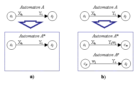
be transition in the automaton A. Now we will define transition and output functions in the component automata.
a) If(si and sj are states of the same component automaton Am), then
is the transition in component automaton Amb) If
(si and sj are states of two different component automata Am and Ap ). Then, the component automaton Am transits from state si to the additional state cm with the output Yt and additional output wj :
How transitions in automaton A are defined in component automata showed on the figure below:

7.5. Reduced Procedure of Decomposition
The procedure of decomposition can be reduced to:
a) copiying row si, sj , X(si, sj), Y(si, sj) from the table of the automaton A to the table of component automaton Am , if si and sj are the states of Am.7.6. Result of Decomposition
b) the replacement of the row si, sj,X(si, sj), Y(si, sj) in the table of automaton A by the row si, cm X(si, sj) Y(si, sj)wi in the table of component automaton Am and the row cp , aj , wj in the table of component automaton Ap, si is the state of Am and sj is the state of Ap; mp.
c) adding row cm, cm to the transition table of component automaton Am.
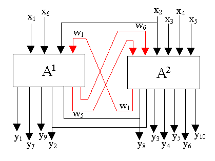
As result of decomposition of our sample automaton A we obtain the network N with two component automata A1 and A2 :

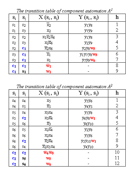
Also we can build transition tables of each component automaton:

Note:
If there three or more signals in additional input (output) signals, then
it is reasonable to code them by binary values. For example, to variables
u1
and u2 are sufficient for coding four inputs wi,
wj,
wk
and ![]() . Also
zero-number state (s0) may be used to represent additional
states (ci) in each of component automata.
. Also
zero-number state (s0) may be used to represent additional
states (ci) in each of component automata.
Last update: 3 August, 2004