Java Applet for Teaching Basics of Test and Diagnostics

Start
the applet
INTRODUCTION
This applet supports action-based
learning via Internet the basics of Digital Test. It offers a set of tools
for understanding the principles of test generation, fault simulation, fault
diagnosis and fault location in digital circuits. A big reservoir of simple
combinational circuits is given to train on the screen in interactive mode
the main important techniques and algorithms. The software provides easy action
and reaction (click and watch), the possibility of distance learning, and
learning by doing.
The work window of this
program consists of three parts - vector insertion panel, view panel for design
schematics, and view panel for test vectors, fault tables and waveforms. Vector
insertion panel has two sub-panels - one for manually inserting vectors and
another one for automated pseudo random test generation. The boxes at the
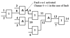
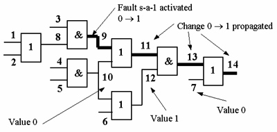
lines on schematics are clickable for inserting proper signals directly on
the internal lines of the circuits to imitate deterministic test generation
procedures.
Fault
Diagnosis
A unit under test (UUT)
fails when its observed behavior is different from its expected behavior.
Diagnosis consists of locating the physical fault(s) in a structural model
of the UUT. The diagnosis process is often hierarchical, carried
out as a top-down process (with a system operating in the field) or bottom-up
process (during the fabrication of the system).
This approach does
most of the work before the testing experiment. It uses fault simulation
to determine the possible responses to a given test in the presence of faults.
The database constructed in this step is called a
fault
table or a fault
dictionary. To locate faults, one tries to match the actual results
of test experiments with one of the precomputed expected results stored
in the database. The result of the test experiment represents a combination
of effects of the fault to each test pattern.
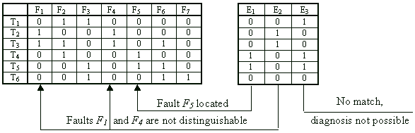
Fault
Table Example
Sequential
Fault Diagnosis Methods
In sequential fault
diagnosis the process of fault location is carried out step by step, where
each step depends on the result of the diagnostic experiment at the previous
step. Such a test experiment is called adaptive testing. Sequential
experiments can be carried out either by observing only output responses
of the UUT or by pinpointing by a special probe also internal control points
of the UUT (guided probing). Sequential diagnosis procedure can be
graphically represented as diagnostic tree.
The diagnostic tree
in the Figure below corresponds to the fault
table example. We can see that most of the faults are uniquely identified,
two faults F1,F4 remain indistinguishable. Not all
test patterns used in the fault table are needed. Different faults need
for identifying test sequences with different lengths. The shortest test
contains two patterns the longest four patterns.
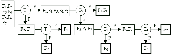
Rather than applying the entire test sequence in a fixed order as in combinational
fault diagnosis, adaptive testing determines the next vector to be applied
based on the results obtained by the preceding vectors. In our example,
if T1 fails, the possible faults are {F2,F3}.
At this point applying T2 would be wasteful, because T2
does not distinguish among these faults. The use of adaptive testing
may substantially decrease the average number of tests required to locate
a fault.
Guided-Probe
Testing
Guided-probe testing
extends edge-pin testing process by monitoring internal signals in the UUT
via a probe which is moved (usually by an operator) following the guidance
provided by the test equipment. The principle of guided-probe testing is
to backtrace an error from the primary output where it has been observed
during edge-pin testing to its physical location in the UUT. Probing is
carried out step-by-step. In each step an internal signal is probed and
compared to the expected value. The next probing depends on the result of
the previous step.
Additional theory
is available here
or here